Lunar Models
Time Machine
modifications
by
Ed Turner
The Rear Lamp
and Dish Support Assembly
| In this article, we will be starting to get down to some real nuts & bolts - the beginnings of some wiring and lighting for the Lunar Time Machine! There is the usual clean-up work to be done on the parts of course. | |
| Pic 1 shows the raw pieces of the rear dish support assembly. |  |
| Pics 2 and 3 show how Lunar has molded these pieces with metal rods embedded in them. The rods were obviously necessary to give strength to the structure in order to support the weight of the dish. There will no doubt be some resin remaining on these metal rods, so it's best to clear it away to expose the bare metal of the rods. It helps to sand them as well, to give the metal more of a 'tooth' for the epoxy to adhere to. | |
 |
 |
| Pic 4 shows the counterweight ready for work. |  |
| Pic 5 shows the lighting kit that will be used to light much of the model. I'm no electronics wiz and have no idea of how to make a circuit board that can cause the lights to flash on this kit, so I opted to cheat a little and found these lighting kits in the craft shop. The kit contsists of ten red, yellow and green flashing LED's on 20 inch lengths of wire that run to a small plastic box with an 'on/off' switch. The lights blink randomly from each other, which will make the effect of individually flashing lights on the control console more effective and similar to the real Machine's flashing lights. True, in the movie the console lights flashed for every day, month and year that went by, but the effect will be similar to this with each of the LED's flashing independently of each other. But, the console work will come later, and for now the concern is the rear dish support light, which will be one of the blinking LED's from this set. |  |
| This set of lights, seen in Pic 6 out of the package, is generally used for decorating Christmas wreaths and the like, but will now be used for making a better Time Machine model. Four out of the ten lights will be needed for the model, so there's a little room for some mistakes if you have any, and 20 inches of wire is plenty to work with. The lights will still work fine after cutting and re-splicing the wires, so choose a red LED from the bunch and cut it from the rest, leaving about 8 to 10 inches of wire-length trailing from the red bulb. Each bulb is attached to a tiny circuit board that will have to be trimmed down using the grinding or sanding bit on the moto-tool. Also, the shape of the LED bulb will have to be slightly altered using the same type of bit. |  |
| Pic 7 shows a close-up of the bulb, the small board it's attached to, and where the bulb has to be tapered, is indicated by arrows. Taper the bottom of the bulb as carefully and closely as you can without damaging the connection. What you want is more of a typical light bulb shape. |  |
| Pic 8 shows the basic shape needed. When you are grinding or sanding the bulb to it's proper shape, the plasic of the LED will appear 'smokey' looking where it's sanded, as opposed to it's original clear, glossy look. Don't worry about this. In fact, carefully sand the entire bulb so the whole thing looks 'smokey'. |  |
| Pics 8 and 8a gives you an idea of the shape, size and how it will be fitted in the fixture, as well as seeing the 'smoked' look of the bulb. That being done, set the bulb aside for the time being. |  |
| Pic 9 shows the counterweight painted in the same deep 'Hunters Green' color paint as the generator housing - it's end-cap painted a gloss black. The end that will be attached to the 'gold ball' should be masked off with some tape while spray painting the green portion of the counterweight - it will later be hand-painted with gold. | 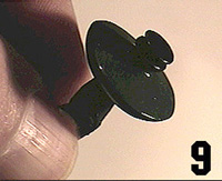 |
| Go to Page 2 | |
Contact us at: The Time Machine Project
If you entered
this page from other than our main page
and you are not in a frame set (no page directory on the left)
Click Here
The Time
Machine Project © 1998 Don Coleman
Web Site © 1999 Don Coleman
Web site created by Don Coleman
3727 W. Magnolia Blvd. #240
Burbank, CA 91505